Support for the STM32F4Discovery board. More...
Detailed Description
Support for the STM32F4Discovery board.
Overview
See this page for a quick getting started guide.
Hardware
MCU
| MCU | STM32F407VGT6 |
|---|---|
| Family | ARM Cortex-M4 |
| Vendor | ST Microelectronics |
| Package | LQFP100 |
| RAM | 192Kb (128Kb RAM + 64Kb CCMRAM) |
| Flash | 1024Kb |
| Frequency | up to 168MHz |
| FPU | yes |
| Timers | 14 (12x 16bit, 2x 32bit [TIM2 + TIM5]) |
| ADCs | 3x 16 channel 6 to 12-bit |
| UARTs | 6 |
| SPIs | 3 |
| I2Cs | 3 |
| Vcc | 2.0V - 3.6V |
| Datasheet | Datasheet |
| Reference Manual | Reference Manual |
| Programming Manual | Programming Manual |
| Board Manual | Board Manual |
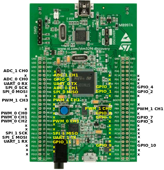
RIOT pin mapping
Please refer to this document for the RIOTs pin mapping for the stm32f4discovery board. The pin mapping is chosen completely arbitrary and can be altered by editing the boards/stm32f4discovery/include/periph_conf.h header file.
User Interface
2 Buttons:
| NAME | USER | RESET |
|---|---|---|
| Pin | PA0 (IN) | NRST |
6 User controllable LEDs:
| NAME | LD3 | LD4 | LD5 | LD6 | LD7 | LD8 |
|---|---|---|---|---|---|---|
| Color | orange | green | red | blue | green | red |
| Pin | PD13 | PD12 | PD14 | PD15 | PA9 | PD5 |
LEDs LD7 and LD8 are used by the USB connector for over-current (LD8) and data (LD7) indication.
Accelerometer
The STM32F4discovery board contains a 3-axis MEMS accelerometer that can sample with up to 1.6kHz.
| Sensor | LIS3DSH |
|---|---|
| Type | Accelerometer |
| Vendor | ST Microelectronics |
| Datasheet | Datasheet |
| Connected to | SPI_0 |
| Pin Config: | |
| Device | SPI1 |
| SCK | PA5 (OUT, SPI1_SCK) |
| MISO | PA6 (IN, SPI1_MISO) |
| MOSI | PA7 (OUT, SPI1_MOSI) |
| INT1 | PE0 (IN) |
| INT2 | PE1 (IN) |
| CS | PE3 (OUT) |
Digital Microphone
The STM32F4discovery board contains a on-board MEMS audio sensor.
| Sensor | MP45DT02 |
|---|---|
| Type | Audio sensor |
| Vendor | ST Microelectronics |
| Datasheet | Datasheet |
| Connected to | n/a |
| Pin Config: | |
| Device | I2S2 |
| CLK | PB10 |
| DOUT | PC3 |
Audio DAC with integrated class D speaker driver
The board contains an digital analog converter (DAC) with integrated class D speaker driver.
| Device | CS43L22 |
|---|---|
| Type | DAC |
| Vendor | Cirrus Logic |
| Datasheet | Datasheet |
| Connected to | DAC + I2C + I2S |
| Pin Config: | |
| Device | DAC1 + I2C1 + I2S3 |
| AIN1 | PA4 (DAC1_OUT) |
| SCL | PB6 (I2C1_SCL) |
| SDA | PB9 (I2C1_SDA) |
| MCLK | PC7 (I2S3_MCK) |
| SCLK | PC10 (I2S3_CK) |
| SDIN | PC12 (I2S3_SD) |
| RESET | PD4 (OUT) |
Supported Toolchains
For using the STM32F4discovery board we strongly recommend the usage of the GNU Tools for ARM Embedded Processors toolchain.
Alternative way to flash
Using openocd to flash the RIOT binary to the board
- Compile your code to have a .hex file
- Connect the board with the mini usb cable, on the debugger side to your PC
- run openocd with
$ sudo /usr/local/bin/openocd -f interface/stlink-v2.cfg -f target/stm32f4x_stlink.cfg - in a new terminal connect:
telnet 127.0.0.1 4444 - run: > flash banks#0 : stm32f4x.flash (stm32f2x) at 0x08000000, size 0x00100000, buswidth 0,chipwidth 0> halttarget state: haltedtarget halted due to debug-request, current mode: ThreadxPSR: 0x21000000 pc: 0x0800251a msp: 0x20000c4c> flash write_image erase unlock /home/c/git/RIOT-OS/RIOT/examples/ipc_pingpong/bin/stm32f4discovery/ipc_pingpong.hex 0auto erase enabledauto unlock enabledtarget state: haltedtarget halted due to breakpoint, current mode: ThreadxPSR: 0x61000000 pc: 0x20000042 msp: 0x20000c4cwrote 16384 bytes from file /home/c/git/RIOT-OS/RIOT/examples/ipc_pingpong/bin/stm32f4discovery/ipc_pingpong.hex in 1.200528s(13.327 KiB/s)> reset
The board is now flashed with your RIOT binary
Using UART
- connect your usb tty to: RX=PA3 TX=PA2 and GND=GND
- PA3 is connected with TX on the UART converter
- PA2 is connected with RX on the UART converter
- done
Known Issues / Problems
I2C
When connecting an I2C device and a logic analyzer to an I2C port at the same time, the internal pull-up resistors are not sufficient for stable bus operation. You probably have to connect external pull-ups to both bus lines. 10K is a good value to start with.
OS X & make term
If you want the terminal to work using make term command and get a message about missing tty device install the driver from https://www.silabs.com/products/development-tools/software/usb-to-uart-bridge-vcp-drivers .
Files | |
| file | arduino_board.h |
| Board specific configuration for the Arduino API. | |
| file | arduino_pinmap.h |
| Mapping from MCU pins to Arduino pins. | |
| file | board.h |
| Board specific definitions for the STM32F4Discovery evaluation board. | |
| file | gpio_params.h |
| Board specific configuration of direct mapped GPIOs. | |
| file | periph_conf.h |
